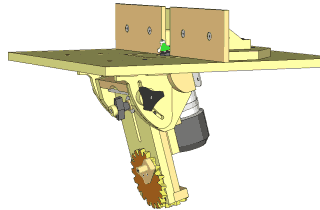
Tilting router lift
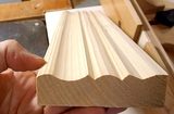
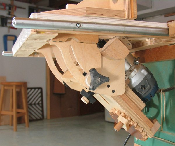 This is my tilting router lift. Being able to tilt a router lift really extends the possibilities for creating interesting molding even when using basic and inexpensive sets of router bits. This is my tilting router lift. Being able to tilt a router lift really extends the possibilities for creating interesting molding even when using basic and inexpensive sets of router bits.
I'm not the first to come up with a tilting router lift, there are even some patents for some designs (fortunately, the patented designs aren't very good, so no risk of infringing). The closest thing on the market that I know of is the Woodhaven 1470 Angle-ease. However, looking at the pictures of that one, it has very limited space where the bit goes, and doesn't allow the motor to come up very high (necessary for some cuts), so it's probably less versatile than this one. There is also the "PR005 Tilt Base" for Bosch Colt palm routers, available from various vendors, including Amazon, but that one also has similar limitations.
Also see my 3D router pantograph
Back to my woodworking website
Building the tilting router lift
Coming up with the design
 My initial idea was to use trunnions as a tilt mechanism for the router lift, especially because I'd just previously come up with an improved method for making trunnions for my homemade bandsaw.But the design I came up with just seemed a bit unwieldy. My initial idea was to use trunnions as a tilt mechanism for the router lift, especially because I'd just previously come up with an improved method for making trunnions for my homemade bandsaw.But the design I came up with just seemed a bit unwieldy.
 But router bits are wide and vary in shape, so there's no point in trying to keep the bit aligned while rotating like you would a saw blade with a slot in the insert. Considering how awkward the trunnion design looked, I decided to use hinges instead. But router bits are wide and vary in shape, so there's no point in trying to keep the bit aligned while rotating like you would a saw blade with a slot in the insert. Considering how awkward the trunnion design looked, I decided to use hinges instead.
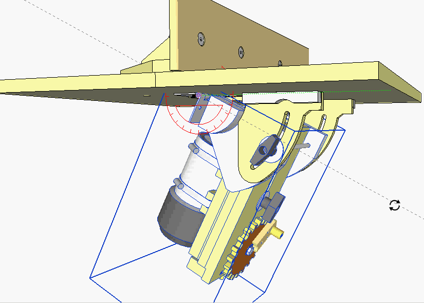
I have mixed feelings about the practicality of using CAD to actually come up with a new design, but in this case, I was able to reject an awkward design without wasting any wood.
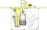
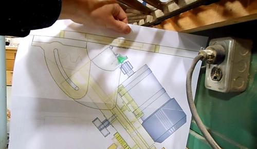 Next I used my BigPrint program to print a large 1:1 picture of the lift onto four sheets of paper, which I glued together. The 1:1 printout gives a better sense of scale. It was also handy for checking how the tilting router lift would fit under the right extension wing of myold table saw. Next I used my BigPrint program to print a large 1:1 picture of the lift onto four sheets of paper, which I glued together. The 1:1 printout gives a better sense of scale. It was also handy for checking how the tilting router lift would fit under the right extension wing of myold table saw.
Building the sliding mechanism
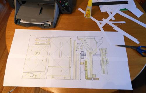 I started by making 1:1 printouts of the various parts from my CAD drawings using myBigPrint program.The 1:1 printouts are very useful as templates for cutting out the curved parts, but they are also useful for quickly checking rectangular parts for size. It helps to give a sense of scale and cuts down on measurement errors. I started by making 1:1 printouts of the various parts from my CAD drawings using myBigPrint program.The 1:1 printouts are very useful as templates for cutting out the curved parts, but they are also useful for quickly checking rectangular parts for size. It helps to give a sense of scale and cuts down on measurement errors.
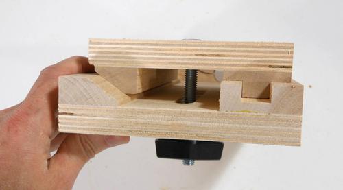 This shows the basic design of the sliding mechanism. A square channel on one side ensures proper alignment, while a beveled track on the other side always pushes the slider to one side so that any play is always taken up on the same side when the knob is tightened. This ensures consistency. This shows the basic design of the sliding mechanism. A square channel on one side ensures proper alignment, while a beveled track on the other side always pushes the slider to one side so that any play is always taken up on the same side when the knob is tightened. This ensures consistency.
 I cut out the square channels by making a series of cuts on the table saw. It's hardly worth putting in the dado blade when making just one part. By making individual cuts, I could tweak the width of the dado that I cut just by bumping the fence by a tiny amount instead of having to mess with dado shims for every adjustment. I cut out the square channels by making a series of cuts on the table saw. It's hardly worth putting in the dado blade when making just one part. By making individual cuts, I could tweak the width of the dado that I cut just by bumping the fence by a tiny amount instead of having to mess with dado shims for every adjustment.
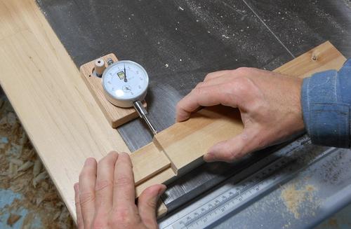 With the square channel cut, checking the amount of lateral play. With the square channel cut, checking the amount of lateral play.
I had about 0.005" of play (0.12 mm). That was a bit more than I was aiming for, but it is necessary to have a few thou of play just to avoid jamming. Just a single coat of varnish on the rails would more than eliminate that amount of play, but I left these unvarnished. In my previous router lift, I initially varnished the rails, and they became too slippery to lock effectively, so I had to scrape the varnish off again.
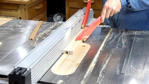
 Cutting the 35 degree bevel for the beveled track. The 35 degree bevel needs to be cut upright against the fence. It's important that the bevel still has a bit of support on the table saw table. Cutting the 35 degree bevel for the beveled track. The 35 degree bevel needs to be cut upright against the fence. It's important that the bevel still has a bit of support on the table saw table.
It would have been easier to start with a piece 2 cm thick instead of 1.6 cm, then cut the bevel, and after that, mill it down to its final thickness. That way there would have been a wider flat part of the workpiece on the table saw table for support.
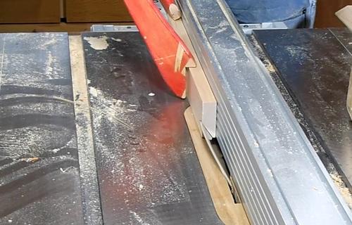
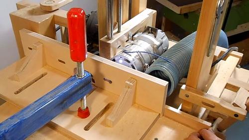
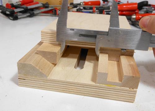 With the outer bevel track attached, the tricky part is getting the inner bevel track at exactly the right lateral position so that the two pieces of plywood will be parallel when pressed together. With the outer bevel track attached, the tricky part is getting the inner bevel track at exactly the right lateral position so that the two pieces of plywood will be parallel when pressed together.
I made sure the two plywood pieces were parallel, pushed the inner bevel track out as far as I could (the beveled track left of the caliper is not glued yet), and then measured the remaining space between the two tracks.
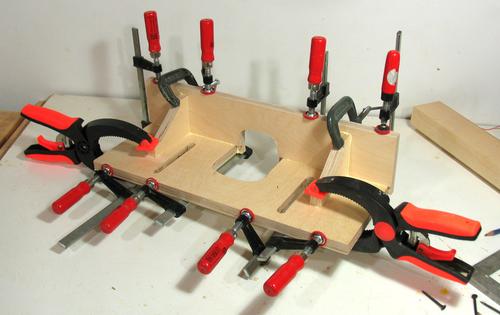
I then made some spacer blocks to hold the inner bevel track at exactly the right position while I glued and clamped it all together.
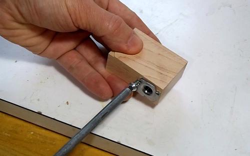 The sliding part of the lift is pushed up and down by a T-nut on a threaded rod. As the rod turns, the nut is screwed up or down. I added a screw to hold the T-nut in the wood. On my previous router lift, I found that sometimes I forgot to unlock the knob when I cranked it down. This had a tendency to pull the nut out of the wood, so a screw to hold it in is a good idea. The sliding part of the lift is pushed up and down by a T-nut on a threaded rod. As the rod turns, the nut is screwed up or down. I added a screw to hold the T-nut in the wood. On my previous router lift, I found that sometimes I forgot to unlock the knob when I cranked it down. This had a tendency to pull the nut out of the wood, so a screw to hold it in is a good idea.
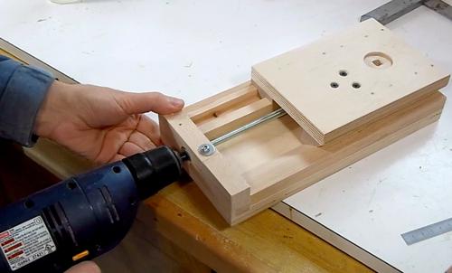 A quick test, spinning the threaded rod with a drill. A quick test, spinning the threaded rod with a drill.
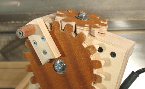
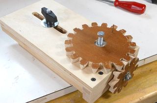
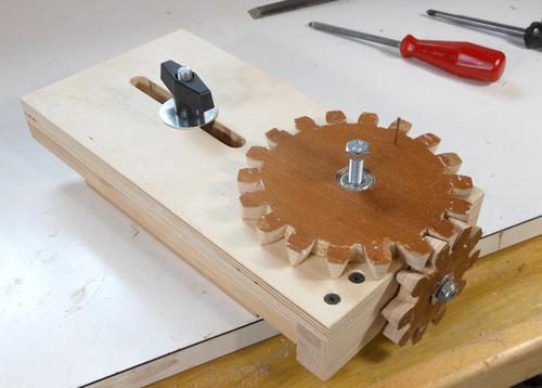 With the gears and locking knob attached. With the gears and locking knob attached.
Making the angle gears
 I wanted a nice number of turns per unit for this router lift. With an 18 turns per inch threaded rod, if I had an 18:10 gear ratio, I would get exactly 10 turns per inch of travel, or about 2.5 mm per turn. An easy number to remember.The most practical way to achieve this ratio was with an 18 tooth and a 10 tooth gear. But with only 10 teeth on the small gear, there was the risk that the fudged gear design I used on my previous router lift might run exceedingly rough. So I came up with a tapered tooth design that also works in theory, not just fudged a little in practice. I wanted a nice number of turns per unit for this router lift. With an 18 turns per inch threaded rod, if I had an 18:10 gear ratio, I would get exactly 10 turns per inch of travel, or about 2.5 mm per turn. An easy number to remember.The most practical way to achieve this ratio was with an 18 tooth and a 10 tooth gear. But with only 10 teeth on the small gear, there was the risk that the fudged gear design I used on my previous router lift might run exceedingly rough. So I came up with a tapered tooth design that also works in theory, not just fudged a little in practice.
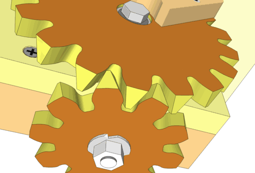
Basically, the sides of the teeth are beveled to match the pressure angle of the adjoining gear. This makes for a relatively elegant right angle meshing, and I checked that the gears would mesh in the CAD program before I built them.
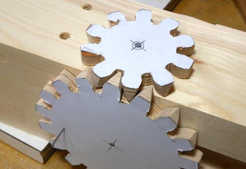
 The gears are designed to have a 14 degree pressure angle, and also have sides that are beveled by 14 degrees towards the other gear. This required "fattening" the teeth on the template so that they wouldn't taper to nothing on the other side. The gears are designed to have a 14 degree pressure angle, and also have sides that are beveled by 14 degrees towards the other gear. This required "fattening" the teeth on the template so that they wouldn't taper to nothing on the other side.
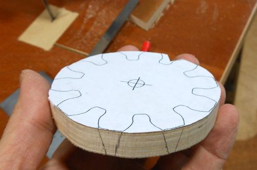
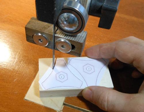
Shown here is my "fattened teeth" paper template glued onto the blank for the 10-tooth gear.
I'll include the fattened gear templates in the plans. If you use an M8 threaded rod (1.5 mm per turn), a good gear pairing would be 16 to 10, to give you exactly 2mm per crank turn. I'll include a 16-tooth template as well.
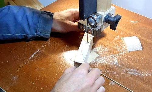
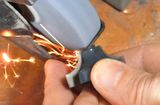
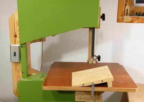 Cutting the teeth requires cutting angles slanted left and right on the bandsaw. Most cast iron frame 14" bandsaws can tilt left by 15 degrees, but my bandsaw does not. So I used a small wedge clamped to the table to get the left tilt. Cutting the teeth requires cutting angles slanted left and right on the bandsaw. Most cast iron frame 14" bandsaws can tilt left by 15 degrees, but my bandsaw does not. So I used a small wedge clamped to the table to get the left tilt.
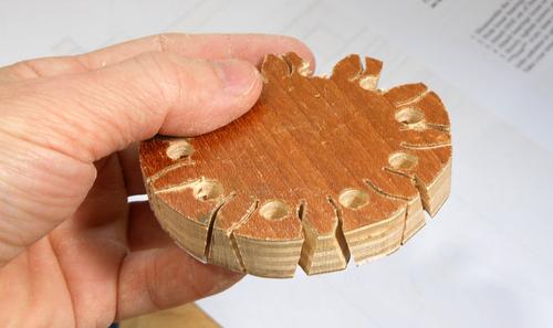 I drilled holes between the teeth, then cut the sides of the teeth, following the lines on the template. The picture at left shows the bottom side of the gear (template side down). But because of the slants, the cuts don't fully line up with the holes on the other side, so I had to make a few more cuts to free up the pieces. I drilled holes between the teeth, then cut the sides of the teeth, following the lines on the template. The picture at left shows the bottom side of the gear (template side down). But because of the slants, the cuts don't fully line up with the holes on the other side, so I had to make a few more cuts to free up the pieces.
 I drilled small pilot holes in both cut gears, nailed them to a piece of timber, and tested the design. Worked perfectly! I drilled small pilot holes in both cut gears, nailed them to a piece of timber, and tested the design. Worked perfectly!
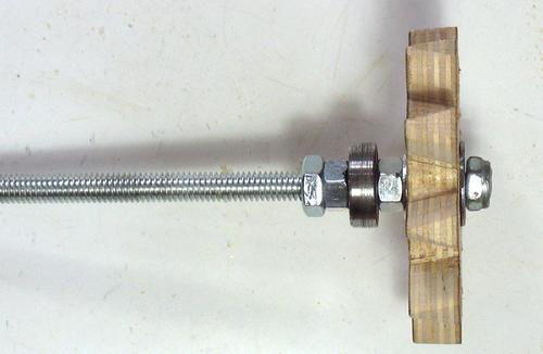 The small gear is mounted on the threaded rod. I inserted a T-nut into the gear, then screwed that onto the threaded rod, with a nut on either side to jam it in place. The roller skate ball bearing is also held in place with a nut on either side. The small gear is mounted on the threaded rod. I inserted a T-nut into the gear, then screwed that onto the threaded rod, with a nut on either side to jam it in place. The roller skate ball bearing is also held in place with a nut on either side.
 A ball bearing goes in the larger gear. The ball bearing isn't really necessary, but roller skate bearings are cheap, so might as well use an extra one. A ball bearing goes in the larger gear. The ball bearing isn't really necessary, but roller skate bearings are cheap, so might as well use an extra one.
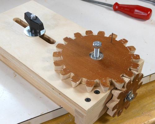
 The gearing, finished and with a crank attached. Some varnish on the gear and gear teeth help them slip against each other. Varnish on the back of the large gear also helps it slip smoothly against the wood. The gearing, finished and with a crank attached. Some varnish on the gear and gear teeth help them slip against each other. Varnish on the back of the large gear also helps it slip smoothly against the wood.
The varnish should also help resist wear, though after two years, I have so far seen no signs of wear on the gears of my other router lift.
Building the router mount
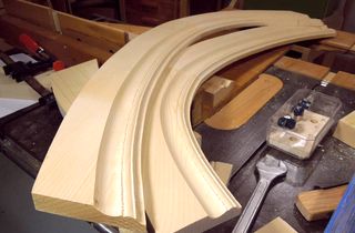
 I cut out the router mounts using templates from the CAD model. On my previous router lift, I cut that curve using a table saw cove cutting technique, but making the mount in two parts on the bandsaw is much easier. I cut out the router mounts using templates from the CAD model. On my previous router lift, I cut that curve using a table saw cove cutting technique, but making the mount in two parts on the bandsaw is much easier.
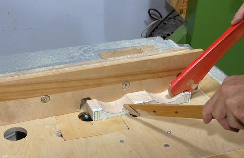 The two pieces for holding the router are still in one part as I route a flat groove in the bottom. It's easier to do that with the two parts still attached together - it's a larger work piece. The hose clamp holding the router will pass through this groove. The two pieces for holding the router are still in one part as I route a flat groove in the bottom. It's easier to do that with the two parts still attached together - it's a larger work piece. The hose clamp holding the router will pass through this groove.
Ironically, I'm using my other router lift to make this cut. You could mount a router to the bottom of a piece of plywood, or just make a series of cuts with the table saw to cut this slot.
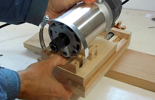 Here's how the router fits with the hose clamps. Here's how the router fits with the hose clamps.
 Some people prefer to build a wooden bracket to hold the router instead of hose clamps. But because I wanted to keep this router lift fairly compact, space around the router is fairly limited, especially as the router is tilted 45 degrees. This is the third time I'm mounting a router with just hose clamps - the mount on my slot mortiser and on my previous router lift have not given me any problems. Some people prefer to build a wooden bracket to hold the router instead of hose clamps. But because I wanted to keep this router lift fairly compact, space around the router is fairly limited, especially as the router is tilted 45 degrees. This is the third time I'm mounting a router with just hose clamps - the mount on my slot mortiser and on my previous router lift have not given me any problems.
Next: Tilting mount, table, and fence
Building the tilting router lift - part 2
Building the tilting mount
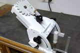
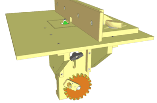
 What makes this router lift a "tilting" router lift is the tilting mount for the sliding mechanism. What makes this router lift a "tilting" router lift is the tilting mount for the sliding mechanism.
The tilting mechanism is really quite a simple affair, consisting of a set of hinges on either side of the router, and brackets for locking the tilt angle in place.
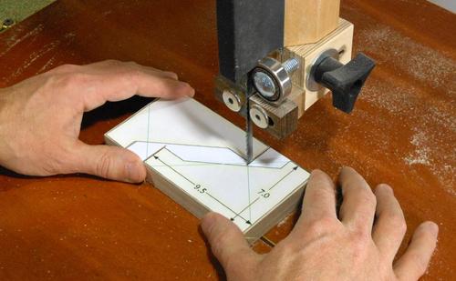
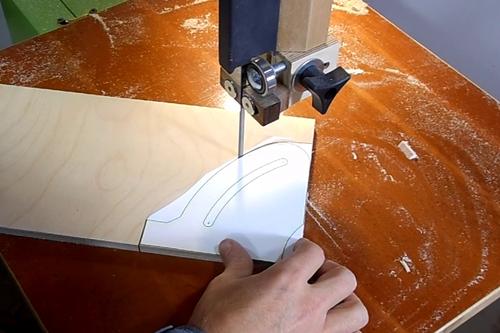 I start by cutting the parts out on the bandsaw using 1:1 printouts from the CAD model. I start by cutting the parts out on the bandsaw using 1:1 printouts from the CAD model.
I used a scroll saw to cut out the curved slot in the tilt lock, but a jigsaw, or a series of overlapping holes would also work.
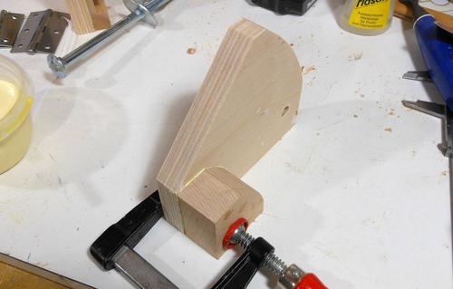 Here's one of the "flanges" that the hinge will mount to. It's made out of 18 mm birch plywood (about 3/4" thick) A block needs to be glued to one end of it to provide more room to attach the hinge. Here's one of the "flanges" that the hinge will mount to. It's made out of 18 mm birch plywood (about 3/4" thick) A block needs to be glued to one end of it to provide more room to attach the hinge.
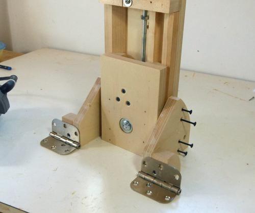 Checking the selected hinges. These are 3" (75 mm) wide hinges. A bit wider than the mounts, but most smaller hinges are made from much thinner metal. I found some 2.5" hinges that were also fairly sturdy, but they were more expensive than the very common 3" door hinges. Checking the selected hinges. These are 3" (75 mm) wide hinges. A bit wider than the mounts, but most smaller hinges are made from much thinner metal. I found some 2.5" hinges that were also fairly sturdy, but they were more expensive than the very common 3" door hinges.
I drilled some extra holes in the hinges because otherwise I could only use two holes against the flanges. After drilling the hole, I used the tip of a larger (3/8" or 10 mm) drill to cut a countersink in the hinge.
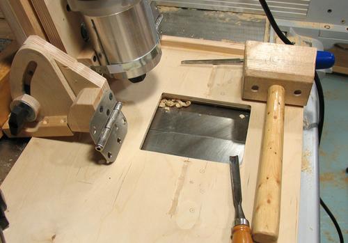 The part around the pin of the door hinge is a bit thicker than the rest of the hinge, so a relief needs to be cut on the mounting flanges and on the table bottom. Here I had just chiseled that relief cut into the bottom of the table. The part around the pin of the door hinge is a bit thicker than the rest of the hinge, so a relief needs to be cut on the mounting flanges and on the table bottom. Here I had just chiseled that relief cut into the bottom of the table.
The table is 18 mm (3/4") Baltic birch plywood.
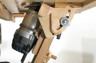
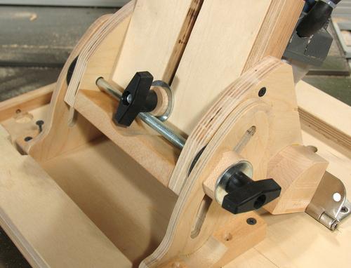 A threaded rod goes all the way across the mount, so that one knob can tighten the flanges on both sides. I initially used an 8" long carriage bolt, and you can see that bolt in some of the pictures. I could only get a bolt that long as a 3/8" bolt. I later swapped the bolt for a 25 cm long piece of 5/16" (M8) threaded rod, seeing that there was threaded rod left over from the lift mechanism anyway. I figure that will make shopping for the screws and such for this project a little easier. A threaded rod goes all the way across the mount, so that one knob can tighten the flanges on both sides. I initially used an 8" long carriage bolt, and you can see that bolt in some of the pictures. I could only get a bolt that long as a 3/8" bolt. I later swapped the bolt for a 25 cm long piece of 5/16" (M8) threaded rod, seeing that there was threaded rod left over from the lift mechanism anyway. I figure that will make shopping for the screws and such for this project a little easier.
Space is very tight around that threaded rod, and I had to put a spacer between the plastic knob and the washer so that the T-bar of the knob would clear the threaded rod.
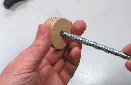 It's best to have a disk firmly attached to one end of the threaded rod. I did this by just drilling a slightly undersized hole in a plywood disk and then twisting that onto the end of the rod. I had to hold the threaded rod in the vise while I twisted on that disk. It holds quite well, but if you aren't fully confident in how the threads hold in wood, you could always add a nut behind the plywood disk. It's best to have a disk firmly attached to one end of the threaded rod. I did this by just drilling a slightly undersized hole in a plywood disk and then twisting that onto the end of the rod. I had to hold the threaded rod in the vise while I twisted on that disk. It holds quite well, but if you aren't fully confident in how the threads hold in wood, you could always add a nut behind the plywood disk.
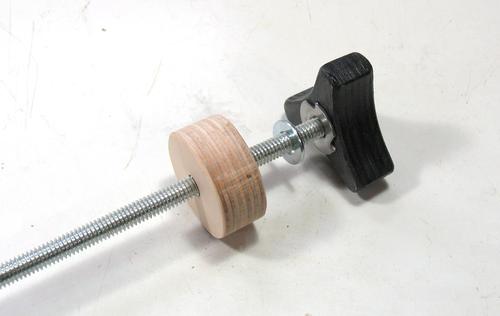 I didn't have any 5/16" bar knobs handy, so I made a wooden knob similar to the ones I made for the fence, but 10% bigger. A T-nut pressed into the knob provides the thread. This lift already uses several 5/16" (M8) T-nuts in other places. The plywood disk in this picture fits loosely on the threaded rod (unlike the one in the previous picture) I didn't have any 5/16" bar knobs handy, so I made a wooden knob similar to the ones I made for the fence, but 10% bigger. A T-nut pressed into the knob provides the thread. This lift already uses several 5/16" (M8) T-nuts in other places. The plywood disk in this picture fits loosely on the threaded rod (unlike the one in the previous picture)
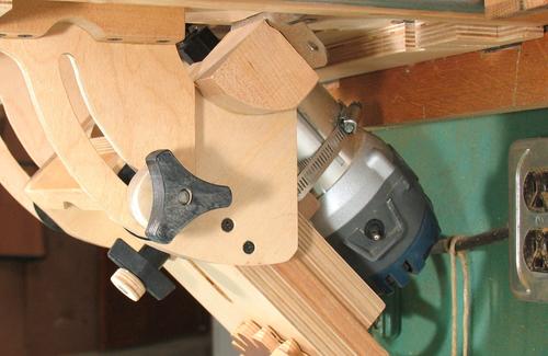
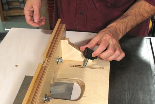
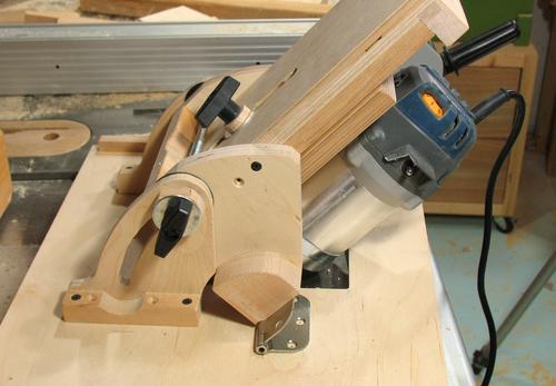 When tilted the full 45-degrees the router comes close to touching the edge of the hole in the table. In fact, the hole is actually 2 cm wider in that direction to better accommodate the router body. When tilted the full 45-degrees the router comes close to touching the edge of the hole in the table. In fact, the hole is actually 2 cm wider in that direction to better accommodate the router body.
 Tilted 45 degrees and all the way up, part of the router body will protrude above the table. This can be a useful configuration for some cuts. Tilted 45 degrees and all the way up, part of the router body will protrude above the table. This can be a useful configuration for some cuts.
Router table top
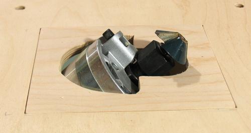
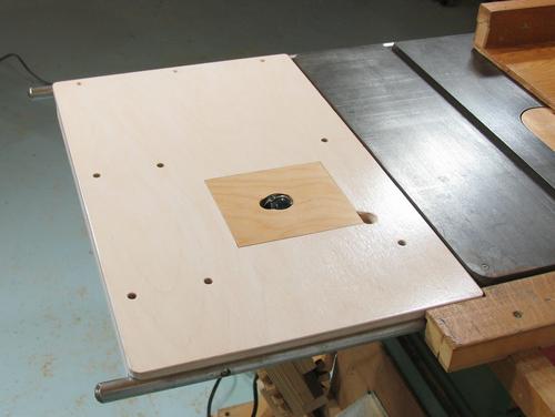 The router table top is made of 3/4" Baltic birch plywood. The router lift is mounted to the bottom of it, and a rectangular insert is inserted from the top. The router table top is made of 3/4" Baltic birch plywood. The router lift is mounted to the bottom of it, and a rectangular insert is inserted from the top.
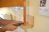
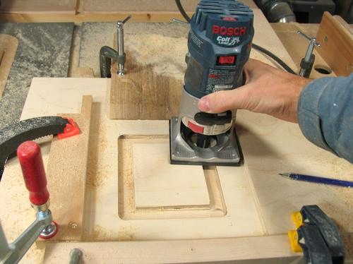 A rectangular opening needs to be cut into the plywood for the insert. I clamped four pieces of wood to the plywood to act as guides for routing the rectangle. A rectangular opening needs to be cut into the plywood for the insert. I clamped four pieces of wood to the plywood to act as guides for routing the rectangle.
I start with a 3/4" (19 mm) square cutter. The guides are placed such that this cutter will cut to the line that marks where the 13x15 cm opening will be.
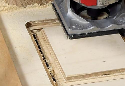 Next switching to a 1/4" (6 mm) wide cutter, but leaving the guides in place, I cut successively deeper until I cut all the way through the plywood. This leaves an opening with a 1/4" or 6 mm ledge all around. Next switching to a 1/4" (6 mm) wide cutter, but leaving the guides in place, I cut successively deeper until I cut all the way through the plywood. This leaves an opening with a 1/4" or 6 mm ledge all around.
 The router motor blows lots of air out the front, and this has a tendency to lift up the insert. I added a tab to one corner of the insert, which hooks below the table. The router motor blows lots of air out the front, and this has a tendency to lift up the insert. I added a tab to one corner of the insert, which hooks below the table.
 I attached a rare earth magnet to the bottom of the table in the opposite corner as the tab. The magnet attracts a screw in the insert to hold it down. I attached a rare earth magnet to the bottom of the table in the opposite corner as the tab. The magnet attracts a screw in the insert to hold it down.
On my previous router lift, I just used a regular door catch magnet, but because this router lift tilts, there wasn't enough room for one of those.
I used a magnet that I reclaimed out of an old hard disk - this saved making a trip to Lee Valley Tools to buy the magnet.
Between the tab in one corner and the screw and magnet in the other, it's enough to hold the insert down against the air blown out of the router.
Router fence
 The fence has two slots that allow it to be clamped in different positions. I'm using my other router lift to cut this slot. But you could rig up a temporary fence to use the router lift you are building to cut this slot. The fence has two slots that allow it to be clamped in different positions. I'm using my other router lift to cut this slot. But you could rig up a temporary fence to use the router lift you are building to cut this slot.
 All the fence parts were cut using paper templates. All the fence parts were cut using paper templates.
 Next gluing the pieces together. On gluing, everything is just butt joints. Next gluing the pieces together. On gluing, everything is just butt joints.
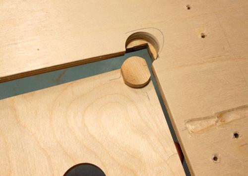
 The gussets are doweled through. So after the glue has dried, I drill a 3.5 cm deep 3/8" (10 mm) hole from the faces into the gusset and then glue in a dowel from the sides. The dowels are cut slightly longer than needed. After gluing, I cut them flush with a chisel.See here for more on that. The gussets are doweled through. So after the glue has dried, I drill a 3.5 cm deep 3/8" (10 mm) hole from the faces into the gusset and then glue in a dowel from the sides. The dowels are cut slightly longer than needed. After gluing, I cut them flush with a chisel.See here for more on that.
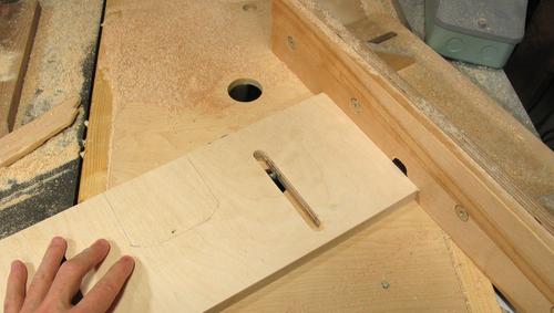
 Cutting the slots for mounting the adjustable fence panels to the front. Cutting the slots for mounting the adjustable fence panels to the front.
I could have cut these on the router table as well, but it was easier to do with my slot mortiser
 Next making the screw knobs for holding down the fence. Again, I start with a paper template.
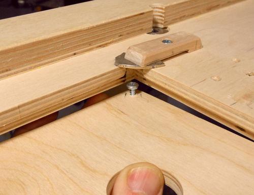
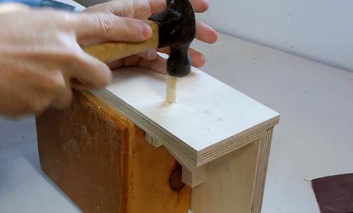
I drilled a hole just smaller than the bolt head in the top of the knobs, about 8 mm deep, with another hole the exact same size as my bolt all the way through. Next I chisel the opening to be hexagonal for the bolt head, but slightly smaller. I marked that hexagon by inserting the bolt into the hole, then hitting the head with a hammer to leave a hexagonal impression in the wood.
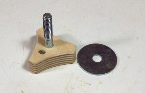 Finished knob with bolt in it. I also drilled a small hole in the bottom of the knob, and inserted a small rare earth magnet in that hole. Finished knob with bolt in it. I also drilled a small hole in the bottom of the knob, and inserted a small rare earth magnet in that hole.
 The idea of the magnet is that it holds the washer in place. That way, when I remove the knobs, the washers stay with the knobs. I also painted the knobs black. The idea of the magnet is that it holds the washer in place. That way, when I remove the knobs, the washers stay with the knobs. I also painted the knobs black.
Next: Making modling with the tilting router lift
Back to the tilting router lift |

|
|
 Timothy Wilmonts's
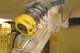 Lee Zimmer's
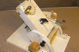 Andrew Scott's
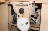 Pekka Svinhufvud's
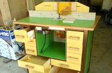 Rudolf Baumeller's
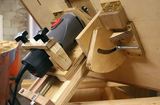 Szczepan Urbanowicz's
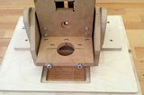 Stephan Billing's
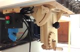 Hans Arkesten's
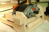 Lars's
 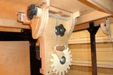 Carsten's router lift
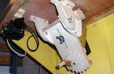 Ryszard grenda's
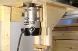
No comments:
Post a Comment