Homemade horizontal boring machine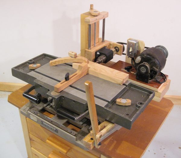 After I built my multi-slot mortising machine, I didn't need my old home-made slot mortising machine anymore. But the XY sliding table that it was based on was too useful a part to be left unused. I originally got the table from a surplus sale. It's totally pre-CNC technology. I found it as a "new product" in a 1968 issue of Popular Mechanics via a Google book search. I also had this fixed drill chuck assembly that I had come across at some point, and between the drill chuck and the XY table, I figured I should be able to build a pretty decent horizontal boring machine. Building the horizontal boring machine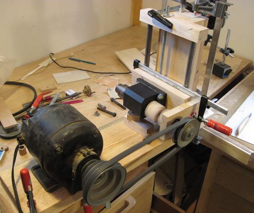 I wanted to power the drill chuck with a belt off an induction motor next to it. In order to mount the motor back far enough to clear the table and work piece, I had to extend the drive shaft of the drill chuck assembly a little bit. I could have just reversed the motor and mounted it facing the other way, but that would have made it harder to mount and also make the motor stick awkwardly out of the back of the machine. I wanted to power the drill chuck with a belt off an induction motor next to it. In order to mount the motor back far enough to clear the table and work piece, I had to extend the drive shaft of the drill chuck assembly a little bit. I could have just reversed the motor and mounted it facing the other way, but that would have made it harder to mount and also make the motor stick awkwardly out of the back of the machine.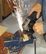 I wasn't sure if my method for extending the shaft would work, so I temporarily rigged up the chuck assembly and drive before gluing anything together for a test. I used a piece of 1/2" drill to extend the shaft. Drill rod is much too hard for setscrews to grip, so I used an angle grinder to grind a keyway into the drill rod. It's always fun to see the sparks flying! Strangely, they don't set sawdust on fire, even if I deliberately shoot them into the sawdust. Though to be cautious, I always make sure that making sparks is not the last thing I do before leaving the workshop. That said, angle grinder sparks most definitely can set stuff on fire at close enough range. I wasn't sure if my method for extending the shaft would work, so I temporarily rigged up the chuck assembly and drive before gluing anything together for a test. I used a piece of 1/2" drill to extend the shaft. Drill rod is much too hard for setscrews to grip, so I used an angle grinder to grind a keyway into the drill rod. It's always fun to see the sparks flying! Strangely, they don't set sawdust on fire, even if I deliberately shoot them into the sawdust. Though to be cautious, I always make sure that making sparks is not the last thing I do before leaving the workshop. That said, angle grinder sparks most definitely can set stuff on fire at close enough range.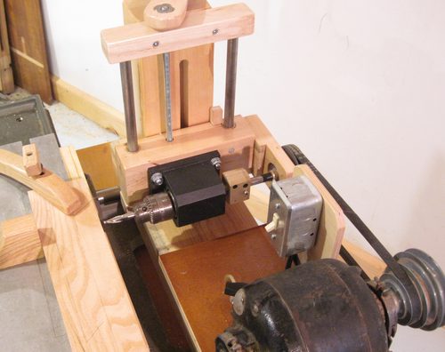 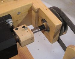 The drill chuck assembly has a 3/4" shaft, and I made a wooden coupling to connect it to the 1/2" drill rod. I figured I might need to make this coupling more robust and maybe line it with rubber to give it more flexibility, but this first try at a coupling is still holding up. So I'll wait for it to break before I make a better one. The drill chuck assembly has a 3/4" shaft, and I made a wooden coupling to connect it to the 1/2" drill rod. I figured I might need to make this coupling more robust and maybe line it with rubber to give it more flexibility, but this first try at a coupling is still holding up. So I'll wait for it to break before I make a better one.The shaft goes through a ball bearing next to the pulley. I didn't have a ball bearing with a 1/2" hole kicking around, but I had one with a 3/4" hole, and I used a bronze sleeve bearing that I had lying around to bring the shaft up to the size of the bearing. I had to sand the sleeve bearing just a little bit to make it fit inside the ball bearing. I found that the bronze sleeve would slowly wander along the shaft towards the coupling, and out of the ball bearing while it was running. So I wrapped some electrical tape around the shaft to keep it in place. The larger ball bearing is also just held in the wood by friction. The hole wasn't exactly the right size, so I wrapped two turns of electrical tape around it to make it fit tight. I was however very careful to ensure that the center of the ball bearing lined up precisely with the axis of rotation of the drill chuck assembly. 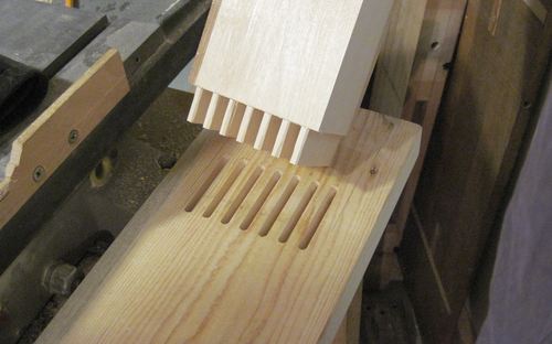 The drill chuck slides up and down along two 5/8" steel shafts on bronze sleeve bearings. The 5/8" steel shafts in turn are attached to a vertical "post" which is attached to the base. Boring can involve substantial forces, and all these forces are transferred through this vertical post. So the post's connection to the base is very critical. The drill chuck slides up and down along two 5/8" steel shafts on bronze sleeve bearings. The 5/8" steel shafts in turn are attached to a vertical "post" which is attached to the base. Boring can involve substantial forces, and all these forces are transferred through this vertical post. So the post's connection to the base is very critical.Maybe I went a little overboard making it a septuple (seven) mortise and tenon joint. I cut the multiple mortises with my slot mortiser, and the tenons with my screw advance box joint jig. Once it was set up, making seven mortises didn't add much effort. 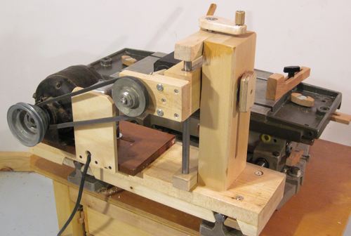 As long as the drill head is only moved up and down within a normal range, the belt doesn't need to be adjusted. But if the head is raised all the way up, the belt tension adjustment needs to be moved to prevent the belt from getting overly tight. As long as the drill head is only moved up and down within a normal range, the belt doesn't need to be adjusted. But if the head is raised all the way up, the belt tension adjustment needs to be moved to prevent the belt from getting overly tight.I have about 15 cm of vertical adjustment range on this machine. Not quite as much as on my slot mortising machine, but enough. 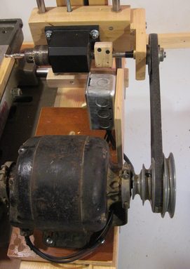 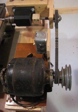 With a stepped pulley on the motor and just a single pulley on the drill head, the motor does need to move forwards and back to make use of the different sized pulleys. The motor mount is held parallel by a protrusion in the base and a slot on the bottom of the motor mount. With a stepped pulley on the motor and just a single pulley on the drill head, the motor does need to move forwards and back to make use of the different sized pulleys. The motor mount is held parallel by a protrusion in the base and a slot on the bottom of the motor mount.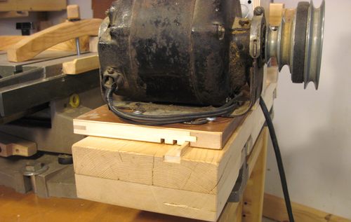 I cut multiple slots in the bottom of the motor mount, so that the motor can be slid side to side in different forward / aft positions. That way, the motor can be aligned so that the various steps of its pulley align with the single pulley on the drill head assembly. This approach worked quite well, and I re-used a simlar scheme for the gear mount on my screw advance box joint jig. I cut multiple slots in the bottom of the motor mount, so that the motor can be slid side to side in different forward / aft positions. That way, the motor can be aligned so that the various steps of its pulley align with the single pulley on the drill head assembly. This approach worked quite well, and I re-used a simlar scheme for the gear mount on my screw advance box joint jig.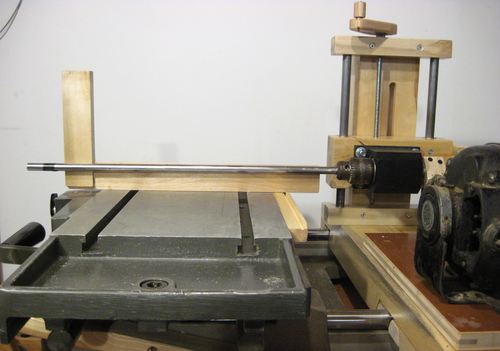 I checked the alignment by mounting a long piece of 1/2" drill rod in the chuck, and checking that it was square and level with the table. Initially, it wasn't quite level. When something doesn't line up right, it's always a matter of figuring out which part most leads to the misalignment and correcting that part. Interestingly, the main source of vertical misalignment was that the holes in the chuck assembly were not drilled precisely. I hadn't drilled those, but had just assumed that they were done accurately in a machine shop. Not so, it turned out. I ended up filing the holes out a little with a chainsaw file to allow me to mount it level. I checked the alignment by mounting a long piece of 1/2" drill rod in the chuck, and checking that it was square and level with the table. Initially, it wasn't quite level. When something doesn't line up right, it's always a matter of figuring out which part most leads to the misalignment and correcting that part. Interestingly, the main source of vertical misalignment was that the holes in the chuck assembly were not drilled precisely. I hadn't drilled those, but had just assumed that they were done accurately in a machine shop. Not so, it turned out. I ended up filing the holes out a little with a chainsaw file to allow me to mount it level.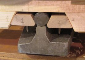 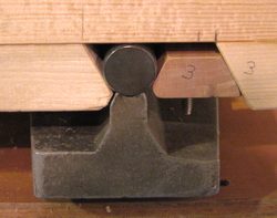 To clamp my drill chuck and motor assembly to the machine, I ended up clamping it to the ends of the rods that the table slides on. This cut down on how much forwards and back motion the table has, but I still have about 15 cm worth of stroke, which is more than enough for my purposes. I came up with this wedging idea to clamp to the steel rods. The trapezoid shaped blocks have t-nuts in them, and screws through the base pull them up against the shaft. The shaft nearest the motor mount only has a wedge on one side. The other "wedge" is part of the base, and serves as a reference. To clamp my drill chuck and motor assembly to the machine, I ended up clamping it to the ends of the rods that the table slides on. This cut down on how much forwards and back motion the table has, but I still have about 15 cm worth of stroke, which is more than enough for my purposes. I came up with this wedging idea to clamp to the steel rods. The trapezoid shaped blocks have t-nuts in them, and screws through the base pull them up against the shaft. The shaft nearest the motor mount only has a wedge on one side. The other "wedge" is part of the base, and serves as a reference.Continue to part 2 of this article
|
Monday, 8 December 2014
Homemade horizontal boring machine
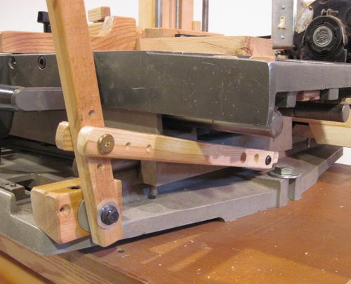 Drilling holes with some drills requires the drill to be pushed into the stock quite hard. So I have a "plunge lever" to help push the table forward and back. I already had a plunge lever assembly just like this when I was using this table as a
 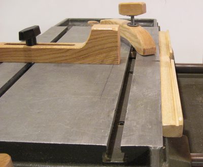 Of course, if the drill needs to be pushed into the stock hard, one also needs to hold the stock very securely in place. This is never much of a problem on a conventional drill press, because the drill just pushes the stock against the table. But on a horizontal boring machine, the work piece likes to slide away from the drill if it's not securely held down against the table.
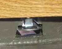 I found this interesting variation on carriage bolt with a really large head, that, if ground flat on two sides, makes for a really convenient mount in the T-slot. Unfortunately, I could only find these up to 5/16" size, and only 2.5" long, so for the longer hold-down bolts, I'm using 4" long 3/8" carriage bolts, with a block of wood on the head of them to slide in the T-slot.
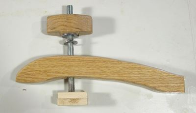 The hold downs are patterned a bit after what would be used in a machine shop, but made out of wood, of course. The one at left uses a 3/8" x 4" carriage bolt. The head of the bolt has a T-profile piece of maple attached to it, to hold it securely in the T-slots of the table.
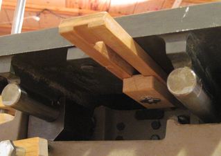
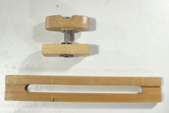 I made some adjustable side-to-side stops. These are useful when pairs of holes need to be drilled at a consistent spacing. It's just a matter of pushing the table up against one or the other stop to get the positions repeatedly. The knobs end up in the trays to either side of the table, just below the surface of the table, and the sliding stop with the elongated slot in it mounts below the table.
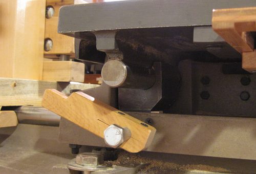 I also added a side to side lock to the table.
 When making multiple dowel joints, its useful to be able to get the lateral position for more than just two holes precisely. I made a series of guides that can be clamped to where the table's templates used to go. This was inspired by a similar feature I saw on a
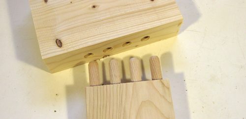 With the vertical position fixed by the drill head height adjustment, and the lateral positions from my guide bar, drilling the holes for multiple dowel joints precisely is quite easy. I would expect a multiple dowel joint with proportions of the one shown at left to be very competitive with mortise and tenon joints for strength. I will have to do an experiment to test this at some point. Last time I did a
 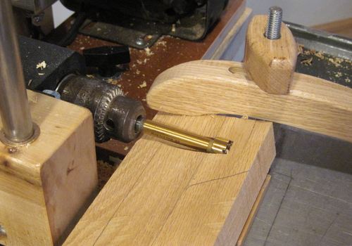 Another thing that I can do with my horizontal boring machine is cut holes that would be difficult on a drill press. With the drill head and the work piece held very securely, as long as my drill is short and stiff enough, I can drill holes that are only partially in the wood, or make things like pocket holes without having any sort of guide for the drill. I can't use the machine to drill pocket holes into the end of a rail though, because the machine would get in the way.
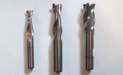 I found that end mills and spiral router bits actually work better at drilling than drills. On account of being short, the bit doesn't flex as much. They also plunge much better than a drill, because unlike a drill, they don't have a lip on the edge or a point in the middle. Drills need the point and the lip to guide them straight and keep the bit from wandering, but with my horizontal boring machine, it's the rigidity of the machine that guides the bit.
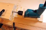 Horizontal boring jig
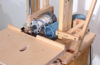 Homemade slot
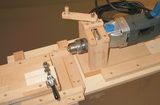
 Using a doweling jig
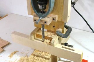 Hollow chisel mortiser experiments
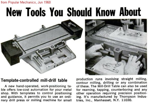
Subscribe to:
Post Comments (Atom)
No comments:
Post a Comment